





News, Blogs & Articles
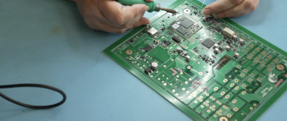
What are printed circuit boards made of?
Case Study
October 15, 2020
Printed circuit boards, otherwise known as PCBs, are the electronic boards that are used in a majority of electronic devices, including phones, household appliances and pieces of medical equipment.
Typically, PCBs are made from non-substrate materials with layers of copper circuitry. However, different types of PCB differ in their construction. For example, while some printed circuit boards contain a single layer of copper circuitry, more advanced PCBs may contain 50 or more.
Generally speaking, there are several different types of PCB. These include popular options such as single sided PCBs, double sided PCBs and multi-layer PCBs. To help you discover more about which option is right for your needs, here we’ll discuss what different PCBs are made from and how they can help you.
Common components of printed circuit boards
Printed circuit boards are made from a variety of PCB materials and electrical components. Common PCB components include:
Resistors
Resistors transmit an electrical current to produce a voltage and dissipate electric power as heat. They come in a range of materials.
Capacitors
The job of a capacitor is to hold an electrical charge within the board and then release it when more power is needed elsewhere in the circuit. Capacitors typically work by collecting opposite charges on two conductive layers that are separated by an insulating material.
Inductors
These are similar to capacitors in that they store energy. However, they are often used to block signals within the PCB, such as interference from another electronic device.
Transistors
A transistor is an amplifier. It’s used to switch or control the electronic signals in a board. There are several different versions of transistors available, but the most common is the bipolar transistor.
Transformers
These are used to transfer the electrical energy from one circuit to another via an increase, or decrease, in voltage.
Diodes
A diode allows the electric current to flow in one direction, but not in the other. As a result, diodes are used to stop the electric current from flowing in the wrong direction and damaging the board and the device. The most popular form of diode is the LED (which stands for light-emitting diode).
Sensors
These devices are used to detect changes in environmental conditions and generate an electrical signal that corresponds to the change. This signal is then sent to other components in the circuit board. Sensors convert a physical element such as light motion, air quality, or sound into electrical energy.
Common PCB layers
Each type of PCB contains a different number of layers that contribute to its functionality. However, no matter which type of PCB you choose, each board contains the same essential foundation. This means that all PCB designs contain the following four layers:
Substrate layer
This is usually made from fibreglass, which gives the board its rigidity. Substrate layers can also be made with epoxies, but these lack the durability that fibreglass provides.
Copper layer
As you’d expect from the name, the copper layer of a PCB is made from a thin layer of copper foil that’s laminated to the board using heat.
When we talk about different ‘layers’ of PCB, we’re talking about how many copper layers they consist of. For example, a single sided PCB will only have one layer of conducting material on one side of the board. In this scenario, the other side of the board is used for incorporating different electronic components. Meanwhile, a double sided PCB will mount the conductive copper and components on both sides of the board.
The thickness of the copper layer will be determined by the amount of power the PCB needs to withstand. PCBs that need to handle a higher level of power will have a thicker level of copper.
Solder mask layer
The solder mask layer is placed on top of the copper and provides most PCBs with their green colour. This layer insulates the copper and ensures that it doesn’t come into contact with any other elements.
Silkscreen layer
The silkscreen layer is primarily added for the benefit of humans. It involves adding letters, numbers and symbols to the board so it’s easier for users to understand the functionality of different pins and LEDs.
What PCBs exist and what are they made from?
A PCB consists of conductive and non-conductive layers that are bonded together. However, the PCB materials used during the manufacturing and assembly processes can differ depending on the purpose of the board and the needs of the client.
Each type of PCB includes different PCB materials. With this in mind, let’s examine the most popular types of PCB in greater detail and outline the main benefits they provide.
Single sided PCB
Single sided PCBs are printed circuit boards that have one layer of conducting material on one side of the board. The other side of the board is then used for incorporating different electronic components. A single sided PCB is made of a substrate layer, a conductive metal layer, a protective solder mask and a silkscreen layer.
Due to their simple design and cost-effective nature, single sided PCBs are incredibly common. Although the manufacturing process is simple, they can still be used in many complex electronic devices, such as stereo equipment, printers and vending machines.
Double sided PCB
Double sided PCBs, which are also known as two-layer boards, allow for more complex designs and circuits.
Unlike single sided PCBs, double sided PCBs can mount the conductive copper on both sides of the board. This allows for closer routing traces.
Components on the two boards are either connected through surface-mount technology or through-hole technology, depending on the needs of your product. All the usual layers that are used in a single sided PCB, such as the substrate, copper layer, silkscreen and solder mask are used for a double sided PCB. However, these are applied to both sides of the board instead of just one.
Due to their ease of use and flexibility, double sided PCBs are very popular. This is partially because they allow for more complex circuitry, which means they can be used in more advanced electronic systems, such as lighting and car dashboards.
Multi-layer PCB
A multi-layer PCB is designed and manufactured using several layers of base material. Generally speaking, multi-layer PCBs feature at least three conductive layers.
These PCBs are constructed using a ‘sandwich model’ that features numerous double-sided conductive layers separated by a corresponding number of insulating material sheets. These are bonded and laminated together under high pressures.
Multi-layer PCBs offer increased functionality for computers, medical equipment and GPS trackers, as well as more complex circuits and devices. In these complex scenarios, they’re often preferred to double sided PCBs because they allow for more complex circuits in a smaller footprint.
Rigid PCB
As the name suggests, rigid PCBs are solid and inflexible. They’re made from several different layers that are joined together using an adhesive and heat. Depending on requirements, rigid PCBs can either be single sided, double sided or multi-layered.
Rigid PCBs are cost-effective and can be produced in large quantities. They’re also incredibly hard-wearing. Due to this, they’re often used in products and industries where it’s vital that components remain fixed.
Flexible PCB
Flexible PCBs, which are also known as ‘flex PCBs’ or ‘flex circuits’ are designed specifically to fit a device or product. As a result, flexible PCBs are often thin, lightweight and can work exceptionally well in small spaces and in contoured shapes.
Flexible PCBs do not use fibreglass for the substrate layer of the board. This is because the material is too rigid. To ensure the board is flexible yet durable, flexible PCBs instead use plastics such as Kapton for the substrate layer.
Flexible PCBs are popular because they do not use as much space as other forms of PCB. They can also withstand extreme temperatures and are compatible with a wide range of components and connectors. On top of this, their inherent flexibility allows them to bend to fit your product.
Rigid-flex PCB
A rigid-flex PCB is a hybrid form of printed circuit board. As a result, it combines elements of both flexible circuit boards and rigid circuit boards. Due to this, rigid-flex PCBs can be folded or continually flexed. In fact, it’s common for the board to be formed into a flexed shape or curve during the manufacturing process.
Rigid-flex PCBs are designed in 3D. This allows for the board to be twisted or flexed into the desired shape. On top of this, rigid-flex circuit boards are usually thinner than other forms of printed circuit boards. With thin copper layers and adhesive-less laminates, a rigid-flex PCB is a small, thin and light solution.
HDI PCB
HDI PCBs, which are also known as high-density interconnect PCBs, are a relatively new form of printed circuit board. However, today, they’re one of the fastest-growing technologies available in the world of printed circuit boards.
HDI PCBs have higher circuitry density compared to more traditional circuit boards. Plus, HDI PCBs also have blind and buried vias, alongside micro vias, which have a smaller diameter. This means that designers are also able to place smaller components closer together on the board, resulting in the quicker transmission of signals and less signal loss or crossing delays.
For these reasons, HDI PCBs are compact and have fewer layers than multi-layer PCBs. However, what HDI PCBs lack in size, they more than make up for in quality. Due to this, they’re popular in advanced technology systems such as smartphones and games consoles.
LED PCB
An LED PCB is a specific type of printed circuit board that’s designed for use in a wide array of lighting modules and applications.
When manufacturing LED PCBs, a number of light-emitting diodes (LEDs) are mounted to a PCB and a complete circuit is formed. This allows for full control of their behaviour through various switches.
Due to this, LED PCBs are used in countless industries to control lighting. For example, they’re used in automotive lighting, street lighting, torches and work lamps.
Blank PCB
A blank PCB is exactly what it sounds like: an empty circuit board that’s free from any of the components that are installed to create a functioning circuit board.
Blank PCBs are also sometimes known as ‘copper-clad circuit boards’ due to the visible layer of copper. This copper plays a vital role. It ensures that the board will have an effective and efficient flow of energy when the components are placed on the board at a later stage.
Although some people believe blank PCBs are made entirely from copper, this is inaccurate. To make sure that blank PCBs remain durable and sturdy, silicon and other materials are also used in the process. These also ensure the PCB is rust-resistant.
Blank PCBs are the fundamental base into which components and parts are secured. These circuit boards are incredibly popular with companies that have the technology available to assemble and manufacture printed circuit boards, but need a blank canvas to start from.
Custom PCB
If it’s better suited to your project and needs, we can also offer a fully bespoke solution in the form of a custom PCB.
Custom PCBs are now a popular solution. This is particularly the case if the design of the PCB needs to be complex, or if the budget needs to be balanced between labour and fabrication costs.
A quality custom PCB will provide you with greater control over every aspect of your circuit layout. Plus, custom PCBs also look far more professional in the eyes of most industry clients and investors.
How to get started with ABL
Here at ABL Circuits, we are experienced in designing all forms of PCBs, including single sided, double sided and multi-layered boards. We either work to client specifications or design and develop PCBs to meet customer specifications and provide advice on the right PCB materials for your project.
From design through to assembly, we can provide total PCB solutions. Plus, when you choose to partner with us, you’ll also benefit from the fastest lead times in the UK. To get started with us, get in touch with a member of the team. Simply fill in the form and we’ll get back to you ASAP.
Get a quote today!
Ready to see exactly how we can help you? Request a quote today. Whether you require bespoke design, manufacturing or PCB assembly, we can help meet and exceed your needs.
FAQ
1. What materials are used to make a printed circuit board?
A printed circuit board (PCB) is primarily made of a combination of materials that provide structural support and electrical performance. The core material is usually a substrate, often made from fibreglass, commonly known as FR-4. This material is lightweight, durable, and has excellent insulating properties. The conductive pathways on the PCB are typically made of copper, which is etched onto the surface of the PCB during the manufacturing process. Other materials like epoxy are used as adhesives to bond different layers of the board, while various coatings may be applied for protection against environmental factors.
2. How is copper used in pcb manufacturing?
Copper is a critical component in electronics and printed circuit board design. It serves as the conductive material that forms the circuit pathways. During the design process, engineers create a pcb layout that includes traces made of copper. In the fabrication phase, excess copper is removed through a process called etching, leaving behind the desired circuit pattern. Copper can be applied in various thicknesses, which influences the electrical performance and thermal conductivity of the printed circuit board.
3. What is the role of a substrate in a printed circuit board?
The substrate is the foundational material of a printed circuit board that provides mechanical support and insulation between the conductive layers. It must have a high dielectric strength to prevent electrical shorts and must be thermally stable to withstand soldering processes. Common substrates include FR-4, polyimide for flexible PCBs, and ceramic for high-frequency applications. Each substrate material is chosen based on the specific requirements of the electronic device it will serve.
4. What types of pcbs are there?
There are several types of pcbs based on their construction and application. These include single-sided boards, which have components on one side only; double-sided pcbs, which have components on both sides; and multi-layer pcbs, which consist of multiple layers of substrate and copper traces stacked together. Flexible pcbs are made from materials that allow them to bend and conform to different shapes.
News, Blogs & Articles


.png)
News
How to Write a Design History File (DHF) When Your CEM Is Involved in Development
April 7, 2026
.png)
News
What a Box Build Specification Document Should Include (And What Most Forget)
April 1, 2026
.png)
News
Why JOSCAR Registration Matters When Choosing a Contract Electronics Manufacturer
March 19, 2026
ABL Circuits have offered a state of the art PCB Manufacturing Service for over 40 years.


ABL Circuits Ltd Icknield Way,
Baldock Hertfordshire, SG7 5BB
United Kingdom


